MorseTaperDimensionsChart.pdf
(For the PDF file, K = B – L)
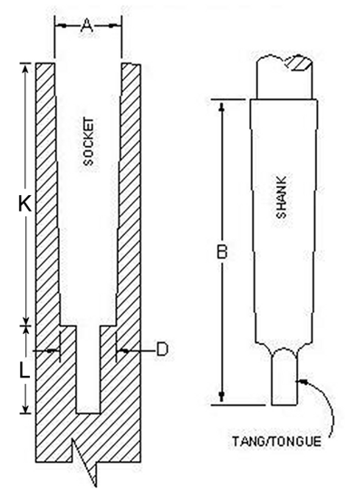
| Taper# | A | D | L | B | K |
| 0 | 0.3561 | 0.2520 | 0.5625 | 2.3438 | 1.7813 |
| 1 | 0.4750 | 0.3690 | 0.7500 | 2.5625 | 1.8125 |
| 2 | 0.7000 | 0.5720 | 0.8750 | 3.1250 | 2.2500 |
| 3 | 0.9380 | 0.7780 | 1.1875 | 3.8750 | 2.6875 |
| 4 | 1.2310 | 1.0200 | 1.2500 | 4.8750 | 3.6250 |
| 5 | 1.7480 | 1.4750 | 1.5000 | 6.1250 | 4.6250 |
| 6 | 2.4940 | 2.1160 | 1.7500 | 8.5625 | 6.8125 |
| 7 | 3.2700 | 2.7500 | 2.6250 | 11.6250 | 9.0000 |
NOTE: At times, the female Morse Taper cavity in a machine may be slightly smaller than the maximum diameters shown above. This is because the MT tooling often extends a bit past the end of the spindle that is receiving the Morse Taper Tool. For Instance, the “A” dimension for a MT2 female cavity may actually measure 0.695″ rather than 0.700″ in extreme cases, etc. The differences in dimensions grow wider as you go from MT0 to MT7.
We can provide adapters for all of these Morse Tapers! Just ask us how.